ODU Resources

You moaned and I responded. Here are just the notes for the ODU section, no questions to put you off. I will move the questions to the Learning Outcome Booklet.

ODU Notes and Practicals

Updated for the 2018 changes

Part 1, containing notes, tutorials and practicals

OUR DYNAMIC UNIVERSE 2018 pdf

OUR DYNAMIC UNIVERSE 2018 word

Part 2 of the notes in word format, you can adapt these if you can open them.

These are part 2 of the notes in pdf format, so you all ought to be able to open them.

OUR DYNAMIC UNIVERSE part 2 

Well after spending 18 months or more several years ago putting everything together students have unanimously declared they want everything separated, so your wish is my command students- here is the complete Our Dynamic Universe section notes with nothing but the essential practicals plus one!

These are part 1 of the notes in pdf format, so you all ought to be able to open them. There is a word version underneath.

These are part 1 of the notes in word format, you can adapt these if you can open them.

New for 2022 KNOWLEDGE ORGANISERS

Teamwork by Mr Stewart (Berwickshire HS) and I. He designed and made them and I tweaked them. Thanks Mr Stewart they’re ace!

Thanks Mr R Stewart- what a team!

Thanks Mr R Stewart!

For those having trouble with Unit 1 part 1 try this little document

1. 1a Equations of motion

1. 1a Equations of motion

I’ve removed the Time Dilation detailed version and added it as a separate document as I suspect most of you wont read them; which is a pity as it makes everything seem fine! Based on Russell Stannard’s excellent book “Relativity- a very short introduction” Oxford. (2008)  ISBN 978–0–19–923622–0)

ODU worked ANSWERS_4 Currently the most up to date version of the worked answers.

ODU worked ANSWERS_4 The pdf version of the most up to date version of the worked answers.

Additional Support

Chapter 1 exam questions B for CFE higher

Chapter 1 exam Answers B for CFE higher

These are powerpoints prepared for the Revised Higher in 2000. They are still relevant now, and talk through example questions. They are great for revision.

It might be old, but sometimes the old ones are the best. Link for the ppp below!

Linked to some talking questions and answer. ppp below

For those struggling with the vectors try these to give you some practice Great Resource from Mr Crookes. Set up your 2 vectors, either use a scale diagram or components and compare to the given answer. Enjoy!

If you don’t like proving v2=u2+2as from v=u+at then use this neat little sheet from Mr Mackenzie.

A lovely little summary from G Gibb!

Equations of Motion

4.4 ODU EqoM 2012 this document has the macros enabled (actually I think you might need to contact me to get the macros, they are not allowed to be uploaded on a WordPress Website. It allows you to check your answers for the acceleration time graphs that you drew from the velocity time graph diagrams.

using displacement equation to prove the last equation

Click on the image to open a power point of Adding Vectors.

Forces, Energy and Power

Momentum

africanfastfood This is an introduction to the momentum topic; think about the collision and where the energy is transferred.

Collisions- Think Safety before buying a car!

Gravitation

Projectiles thanks to Mr. Rossi for this one.

Battleships & AWACS Projectiles thanks to Mr. Rossi for this one too.

Special Relativity

Time dilation02

Cleonis [CC BY-SA 3.0 (http://creativecommons.org/licenses/by-sa/3.0/)]

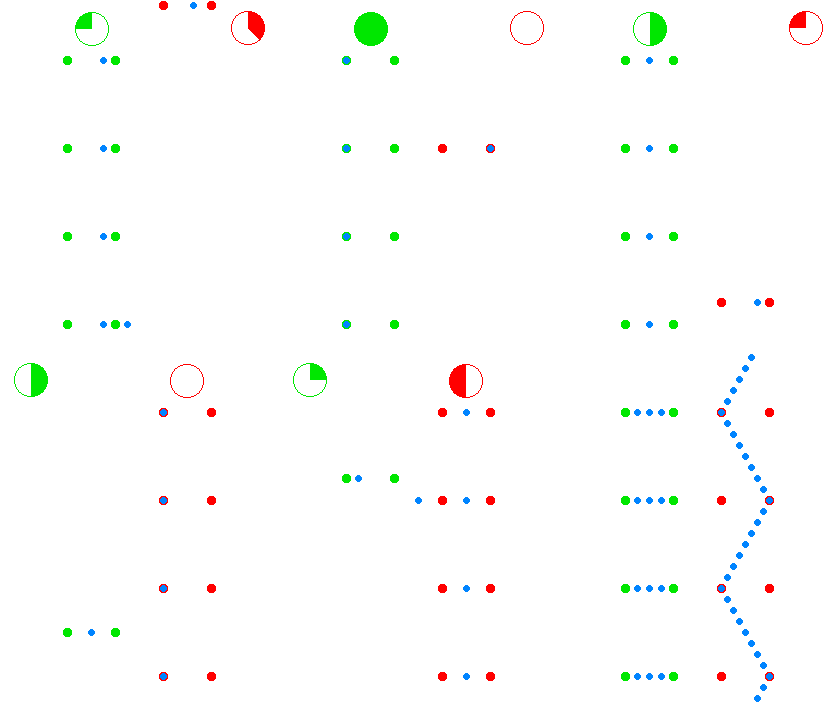
The green dots and red dots in the animation represent spaceships. The ships of the green fleet have no velocity relative to each other, so for the clocks onboard of the individual ships, the same amount of time elapses relative to each other, and they can set up a procedure to maintain a synchronized standard fleet time. The ships of the “red fleet” are moving with a velocity of 0.866 of the speed of light with respect to the green fleet.

The blue dots represent pulses of light. One cycle of light-pulses between two green ships takes two seconds of “green time”, one second for each leg.

{\displaystyle {\sqrt {3}}}

As seen from the perspective of the reds, the transit time of the light pulses they exchange among each other is one second of “red time” for each leg. As seen from the perspective of the greens, the red ships’ cycle of exchanging light pulses travels a diagonal path that is two light-seconds long. (As seen from the green perspective the reds travel 1.73 ({\displaystyle {\sqrt {3}}}) light-seconds of distance for every two seconds of green time.)The animation cycles between the green perspective and the red perspective, to emphasize the symmetry.

OnVelocities This is a document referred to in the Research Task in the ODU part 2 notes.

PHYSICS WORLD ARTICLE DECEMBER 2009 This is a document referred to in the Research Task in ODU part 2 notes

The Expanding Universe

The expanding universe powerpoints. Might not be quite the final version

This is the pdf version of the powerpoint

The above is the pdf version of the powerpoint

Are we missing something in the Expanding Universe?

AH (Doppler)– some of this is relevant to Higher.

HOMEWORK

The homework booklets are now in the HOMEWORK section.

Homework Booklet Complete pp6-8 (first question), 10-16, 18. Complete notes on Units prefixes and Sci Notation, Uncertainties, Equations of Motion. Read up on Forces.

Updated August 2019
Signature

Quantity, Symbol, Unit, Unit Symbol

Comments from the Workshop

Revision

Clicking on the link above will take you to the You Must Justify Questions that we didn’t have time for! Please look over this.

Flashcards

CfE Higher Revision Cards A4

Quantity, Symbol, Unit, Unit Symbol

I’ve put together, with Mrs Mac’s help, a document with quantity, symbol, unit and unit symbol so that you know the meaning of the terms in the Relationships Sheet. It is in EXCEL so that you can sort it by course, quantity or symbol.

Quantity, Symbol, Units the excel sheet

Quantity, Symbol, Units a pdf sheet sorted by course and then alphabetical by quantity.

This is the same information in readily available Tablepress form. If you click on the Higher tab at the top it should sort by terms that you need in alphabetical order, or search for a term. Let me know if I’ve missed any.

Quantity, Symbol, Unit, Unit Symbol Table for N5-AH

NHAPhysical Quantity symUnitUnit Abb.
5absorbed dose D gray Gy
5absorbed dose rate H (dot)gray per second gray per hour gray per year Gys-1 Gyh -1 Gyy-1
567acceleration a metre per second per second m s-2
567acceleration due to gravity g metre per second per second m s -2
5activity A becquerel Bq
567amplitude A metre m
567angle θ degree °
567area A square metre m 2
567average speedv (bar)metre per second m s-1
567average velocity v (bar)metre per second m s -1
567change of speed ∆v metre per second m s -1
567change of velocity ∆v metre per second m s-1
5count rate - counts per second (counts per minute) -
567current I ampere A
567displacement s metre m
567distance dmetre, light year m , ly
567distance, depth, height d or h metre m
5effective dose H sievert Sv
567electric charge Q coulomb C
567electric charge Q or q coulomb C
567electric current I ampere A
567energy E joule J
5equivalent dose H sievert Sv
5equivalent dose rate H (dot)sievert per second sievert per hour sievert per year Svs-1 Svh-1 Svy -1
567final velocity v metre per second m s-1
567force F newton N
567force, tension, upthrust, thrustF newton N
567frequency f hertz Hz
567gravitational field strength g newton per kilogram N kg-1
567gravitational potential energy Epjoule J
5half-life t1/2 second (minute, hour, day, year) s
56heat energy Eh joule J
567height, depth h metre m
567initial speed u metre per second m/s
567initial velocity u metre per second m s-1
567kinetic energy Ek joule J
567length l metre m
567mass m kilogram kg
5number of nuclei decayingN - -
567period T second s
567potential difference V volt V
567potential energy Ep joule J
567power P watt W
567pressure P or p pascal Pa
5radiation weighting factor wR- -
567radius r metre m
567resistance R ohm Ω
567specific heat capacity c joule per kilogram per degree Celsius Jkg-1°C -1
56specific latent heat l joule per kilogram Jkg-1
567speed of light in a vacuum c metre per second m s-1
567speed, final speed v metre per second ms -1
567speed, velocity, final velocity v metre per second m s-1
567supply voltage Vsvolt V
567temperature T degree Celsius °C
567temperature T kelvin K
567time t second s
567total resistance Rohm Ω
567voltage V volt V
567voltage, potential difference V volt V
567volume V cubic metre m3
567weight W newton N
567work done W or E Wjoule J
7angle θ radian rad
7angular acceleration aradian per second per second rad s-2
7angular displacement θ radian rad
7angular frequency ω radian per second rad s-1
7angular momentum L kilogram metre squared per second kg m2s -1
7angular velocity,
final angular velocity
ω radian per second rad s-1
7apparent brightnessbWatts per square metreWm-2
7back emfevolt V
67capacitance C farad F
7capacitive reactance Xcohm W
6critical angle θc degree °
density ρ kilogram per cubic metre kg m-3
7displacement s or x or y metre m
efficiency η - -
67electric field strength E newton per coulomb
volts per metre
N C-1
Vm-1
7electrical potential V volt V
67electromotive force (e.m.f) E or ε volt V
6energy level E1 , E2 , etcjoule J
feedback resistance Rfohm Ω
focal length of a lens f metre m
6frequency of source fs hertz Hz
67fringe separation ∆x metre m
67grating to screen distance D metre m
7gravitational potential U or V joule per kilogram J kg-1
half-value thickness T1/2 metre m
67impulse (∆p) newton second
kilogram metre per second
Ns
kgms-1
7induced e.m.f. E or ε volt V
7inductor reactanceXLohm W
7initial angular velocity ω oradian per second rad s-1
input energy E ijoule J
input power Piwatt W
input voltage V1 or V2 volt V
input voltage V ivolt V
6internal resistance r ohm Ω
67irradiance I watt per square metre W m-1
7luminoscityLWattW
7magnetic induction B tesla T
7moment of inertia I kilogram metre squared kg m2
67momentum p kilogram metre per second kg m s-1
6number of photons per second per cross sectional area N - -
number of turns on primary coil np- -
number of turns on secondary coil ns- -
6observed wavelengthλobservedmetrem
output energy Eo joule J
output power Powatt W
output voltage Vo volt V
6peak current Ipeak ampere A
6peak voltage V peak volt V
7phase angle Φ radian rad
67Planck’s constant h joule second Js
7polarising angle
(Brewster’s angle)
ipdegree ̊
power (of a lens) P dioptre D
power gain Pgain - -
7Power per unit areaWatts per square metreWm-2
primary current Ip ampere A
primary voltage Vpvolt V
7radial acceleration ar metre per second per second m s-2
6redshiftz--
67refractive index n - -
6relativistic lengthl'metrem
6relativistic timet'seconds
rest mass mo kilogram kg
6rest wavelengthλrestmetrem
6root mean square current I rmsampere A
6root mean square voltage Vrmsvolt V
7rotational kinetic energy Erotjoule J
7schwarzchild radiusrSchwarzchildmetrem
secondary current Is ampere A
secondary voltage Vsvolt V
7self-inductance L henry H
67slit separation d metre m
7tangential acceleration atmetre per second per second m s-2
6threshold frequency fohertz Hz
7time constanttseconds
7torque Τ newton metre Nm
7uncertainty in Energy∆E jouleJ
7uncertainty in momentum∆px kilogram metre per second kgms-1
7uncertainty in position∆x metre m
7uncertainty in time∆t seconds
6velocity of observer vometre per second m s-1
6velocity of source vsmetre per second m s-1
voltage gain - - -
voltage gain Ao or V gain - -
567wavelengthλmetrem
6work functionWjouleJ


Revision Plan

28/02/18. If you’re stuck inside- DON’T go on your X-boxes, PS4 or whatever the latest number try doing some timed papers.

To the student’s sister who needs the Quantity, Units, Symbols etc .I’ve uploaded the old pre-CfE version and you can just add the additional few. Check out Int1-AH many are relevant. Missing would be t’, l’ etc.

quantity symbol sheet 

If there is a snow day tomorrow, use the time to look at the EMF material and the test will be as soon as we get back.

__________________________________

This is a ten week revision plan, put together by Mr A Riddell from “up North”. It will give you some ideas on how to break up the daunting task of revision. You don’t have to complete this in the same order, but it does give an indication of how much you need to cover in one week.

Study Plan Higher Physics word

Study Plan Higher Physics pdf


Signature


What is the Biggest Ever Redshift?

A discussion on the Physics Teachers’ Network requested advice on “What is the biggest ever redshift detected?”

Research shows it was a redshift, z = 11.09 for galaxy GN-z11; and the measurements were  taken in the near infra red using Hubble’s Wide Field Camera. 

This is a big question because effectively we are seeing the furthest galaxy back in time.  It is 32.2 billion years away and came into existence 400 million years after big bang.  So if the Universe is only 13.8 billion years old then how come we can see something so far away?

During this time the Universe was opaque and full of neutral atoms.

Professor Martin Hendry supplied an interesting reply.

In some cases we can determine the redshift of a galaxy by measuring the wavelength of a particular spectral line that corresponds to a particular transition of an electron in a hydrogen atom.  For example the Lyman alpha emission line is the result of an electron dropping down from the n=2 energy level to the n=1 energy level, and the presence of this spectral line is often seen as an indicator of a recent burst of new stars forming as one might expect to see in a very young, recently formed galaxy.  (This line was proposed as a tell-tale sign of a very young galaxy by Bruce Partridge and Jim Peebles – awarded the Nobel Prize for physics this week: see e.g. https://en.wikipedia.org/wiki/Lyman-alpha_emitter).  This line has a wavelength of 121.567 nm in the rest frame of the hydrogen atom.  If a galaxy is a strong Lyman alpha emitter, and the line is observed at wavelength lambda, then by comparing the observed wavelength with the 121nm at which it was emitted we can measure the redshift of the galaxy.

(Of course if this spectral line is redshifted then how do you know it’s a Lyman alpha line?  Likewise for any other spectral line.  Often it’s the combination of several spectral lines and their relative spacing that gives the game away – a bit like a bar code in the supermarket.  You could imagine enlarging the image of a bar code in a photocopied and, generally, it’d still be recognisable as the overall pattern would still be the giveaway).

In fact for this record-holding galaxy, the redshift was determined a slightly different way, from the Lyman series but not the Lyman alpha line and not from an emission line but an *absorption* line: specifically it was determined from the “Lyman break” – i.e. the limiting wavelength that corresponds to the amount of photon energy you need to absorb to allow an electron in the n=1 energy level to escape from its hydrogen atom altogether.   That is a higher energy (and so a higher frequency, and a shorter wavelength) than the Lyman alpha line, and in fact corresponds to about 91 nm in the rest frame of the hydrogen atom.   Any photons that have even higher energies (and thus even shorter wavelengths) than this get absorbed by the (lots of) neutral hydrogen that is around in the Universe at that time; these photons thus *ionise* that neutral hydrogen.  This is sometimes referred to as “re-ionisation” in the sense that the universe was fully ionised when it was much younger, because it was much hotter, then it cools enough for neutral hydrogen to form – i.e. when the CMBR was emitted – and now it’s being ionised again.  Where are the high-energy photons coming from to do this ionising (being absorbed in the process)?  They are believed to come from hot young stars – i.e. the newly formed stars in these young galaxies.  (Remember, the more massive the star the hotter their surface temperature, so massive blue stars emit lots more of these energetic photons than cooler red stars do).

So, in summary, the spectrum of light from a galaxy as a whole drops off at the Lyman break, like a “cliff edge” because at shorter wavelengths than the Lyman break these photons get absorbed, ionising the hydrogen gas in their environments.

You can then play the same game as with an emission line: look for where this “cliff edge” appears in the observed spectrum and then use that observed wavelength (which will be much longer than 91nm) to estimate the redshift.

The research paper on GN-z11 is at https://arxiv.org/pdf/1603.00461.pdf, and is actually pretty readable I think…

Other references:

https://www.youtube.com/watch?v=vIJTwYOZrGU

https://www.space.com/32150-farthest-galaxy-smashes-cosmic-distance-record.html

Another clear explanation from Prof. Hendry, who never makes us teachers feel silly for asking questions. Thanks to Mr Thomson and his student for the original question.

Tips!

Here I will post a few tips and hints to remember when answering SQA Higher Papers, hopefully they’ll be quick, snappy and memorable. You’ve got the whole of the Scottish Physics Teachers’ Community Wisdom Below!

  1. How to remember Cosmic Microwave Background Radiation (spell the whole lot not CMBR, as this isn’t a name) However, the way to remember CuMBRia.
  2. Conservation of Momentum IN THE ABSENCE OF EXTERNAL FORCES, MOMENTUM BEFORE THE COLLISION IS EQUAL TO THE MOMENTUM AFTER THE COLLISION.
  3. Obviously you know- no secs in Physics, just stick to unit symbols and save all the problems of spelling.
  4. Fundamental Particles: Key point: it is not that they can be used to make bigger ‘things’, but rather that they are not made from smaller things.
  5. Strong force (associated with the gluon) acts over a very short distance.
  6. The gravitational force extends over very large/infinite distances.
  7. Neutrons don’t carry/have (net) charge so cannot be accelerated/guided/ deflected by magnetic fields.
  8. Remember: SIG FIG, your final answer should be rounded up to the same number of significant figures as the LEAST significant measurement.
  9. Don’t forget to revise your uncertainties.
  10. Make sure you see the words “end of question paper”. Don’t assume you’ve got to the end and there are no questions on the very last page!
  11. “Show” questions – means show correct formula, working and numerical answer stated as given in the question.
  12. Don’t leave anything blank! If you really don’t know, give it a go – you never know.
  13. The questions in the exam sections (MC and then extended answers) are in approximately the same order as the equation sheet.
  14. LIST: given numbers with the correct symbols before doing a calculation. Or as we say IESSUU (information, Equation, Substitution, Solution, Units and Underline)
  15. Substitute then rearrange.
  16. Read all of the question, especially that bit you skipped over at the start.
  17. Don’t forget units! It’s now worth at least 33% of a calculation!
  18. This will do for now more to come as they arise……Check out the past paper marking instructions for do’s and  don’ts- its full of them in that second column!

Here are some top tips for Revision from Mr Dawson from Wallace Hall Academy- thanks

H Revision Pupil Questions pdf version

H Revision Pupil Questions word version

img src=”https://s.gravatar.com/avatar/e1515b0c027eaeaaa7232dae92981146?s=80″ /> Signature


Special Relativity

Resources for Special Relativity

Here is a link to a fantastic little book that started me on my “very short introduction” library. It has been uploaded as a pdf file, but if you enjoy it give the author some credit and pay the guy (Russell Stannard) by buying it!

Relativity-A-Very-Short-Introduction.pdf

Frames of Reference

You should all try to make your holiday videos so useful in showing Physics ideas! Who is in motion? Does it remain the same throughout the sequence?


This is covered in the web-based research post but I’ve uploaded it here as an MP4 file.

Just check this off against the content as it isn’t all covered at Higher (some is the AH and some isn’t covered at all).

Neil deGrasse Tyson with his inimitable style explains the Michelson-Morley experiment and shows that despite getting a rubbish result it doesn’t say your results are rubbish! This was big Science progress and it wasn’t explained until Einstein came along. It was the turning point that transformed Science.

Here are further explanations of the Michelson-Morley experiment and a hint of more of the course to come.

Evidence for Special Relativity

Sixty symbols- Nottingham University

Sixty Symbols by Nottingham University are an amazing set of videos, although far more than sixty by now. Check out and keep watching.

…. and here at the end I have uploaded the worked answers (thanks to whoever wrote these excellent questions) so that you can check off your tutorials.

ODU worked ANSWERS_5

Our Universe tutorial solutions

Signature

updated October 2019


Higher Past Papers

These papers and marking instructions are reproduced to support SQA qualifications, please check the conditions of use and ensure they are not used for commercial benefit.

National Qualification Higher Physics Papers

Digital Paper
(spell)
Higher
Paper
YEARMIExam
Report
tagging xls2015- 2022tagging pdfskills tagging
2023P1 DQP
2023P2DQP
2023ABDQP
2023P1

2023P2
2023
2023P1MI

2023P2MI
RelationS2023
2023AB

2022 P1DQP
2022P2DQP
P1 2022
P2 2022
Grid 2022
2022 2022P1MI
2022P2MI
2022Report
P1 2021
P2 2021
Grid 2020
20212021P1MI
2021P2MI
keymessages
2019 DQPNH 201920192019MI2019 Report
SpecP1
Spec P2
SpecP1MI
P2MI
2018 DQPNH 201820182018MI2018 Report
2017 DQPNH 201720172017MI2017 Report
2016 DQPNH 201620162016MI2016 Report
2015 DQPNH 201520152015MI2015 Report
H S1 DQP
H S2 DQP
NH SpecSpecSpecMI
Physics
marking
general
principles
READ
THIS!
MARK GUIDE

If you’d like to work through past papers by topic then Mr Davie has done all the hard work for you and has promised to keep this list up to date. He says

http://bit.ly/HigherPhysics18

Below are the Revised Higher Past Papers, the content is very very similar to the new National (CfE) Higher, although the marks would be different. These were the last past papers with half marks!

Higher
Paper
YEARMIExam Feedback
H Rev 20152015MI Rev 20152015 Report
H Rev 20142014MI Rev 20142014 Report
H Rev 20132013MI Rev 2013
2013 Report
H Rev 20122012MI Rev 20122012 Report
H Rev SpecSpecimen
Paper
MI Rev Spec
READ
THIS
MARK GUIDE

These are the traditional Higher Past Papers (once also known as revised!) Remember some of this material is no longer on the syllabus, and some is relevant to National 5.

Higher
Paper
YEARMarking
Instructions
Exam
Feedback
H 20152015MI 20152015 Report
H 20142014MI 20142014 Report
H 20132013MI 20132013 Report
H 20122012MI 20122012 Report
H 20112011MI 20112011 Report
H 20102010MI 20102010 Report
H 20092009MI 20092009 Report
H 2008 2008MI 20082008 Report
H 20072007MI 20072007 Report
H 20062006MI 20062006mcH&Int2 stats2006 Report
H 20052005MI 20052005 Report
H 20042004MI 20042004 Report
H 20032003MI 20032003 Report
H 20022002MI 20022002 Report
H 20012001MI 20012001 Report
H 20002000MI 2000
Internal report

U Standards 2000
H Rev Specimen QPSpecimenMI H Rev Specimen

From National Parent Forum of Scotland This great little pdf file gives some ideas of suitable questions from the traditional Higher papers that are suitable for the new National Qualifications.

Thanks to Mr John Irvine and Mr Stuart Farmer for the course reports.

PLEASE both teachers and students READ the Report after tackling the past paper. The course reports give really good background and information about how candidates performed in the exam and what messages you should learn from them.

Higher
Paper
YEARMarking
Instructions
1999H 1999 PI Solutions
H 1999 PII Solutions
1998H 1998 PI Solutions
H 1998 PII Solutions
1997H 1997 PI Solutions
H 1997 PII Solutions
1996H 1996 P1 Solutions
H 1996 PII solutions
1995H 1995 PI Solutions
H 1995 PII Solutions
1994H 1994 PI Solutions
H 1994 PII Solutions
1993H 1993 PI Solutions
H 1993 PII Solutions
1992H 1992 PI solutions
H 1992 PII Solutions
1991

All the best with your revision!

Signature
September 2020

Uncertainties

New for 2022 KNOWLEDGE ORGANISERS

Teamwork by Mr Stewart (Berwickshire HS) and I. He designed and made them and I tweaked them. Thanks Mr Stewart they’re ace!

Contains UPSN, OEQ, Uncertainties and is 4 pages

It is really important that you get to grips with the uncertainty section. You will need this information for your Assignment and it could well form a question on the exam paper.

The key is remembering that ANY measurement is liable to uncertainty. Get that and you’re half way there!

Here is a summary of Key Knowledge for this section new for 2021

CONTENT ASSOCIATED WITH UNCERTAINTIES

Random and systematic uncertainty

Uncertainties and data analysis

  • All measurements of physical quantities are liable to uncertainty, which should be expressed in absolute or percentage form. Random uncertainties occur when an experiment is repeated and slight variations occur. Scale reading uncertainty is a measure of how well an instrument scale can be read. Random uncertainties can be reduced by taking repeated measurements. Systematic uncertainties occur when readings taken are either all too small or all too large.
  • They can arise due to measurement techniques or experimental design.
  • The mean of a set of readings is the best estimate of a ‘true’ value of the quantity being measured. When systematic uncertainties are present, the mean value of measurements will be offset. When mean values are used, the approximate random uncertainty should be calculated. When an experiment is being undertaken and more than one physical quantity is measured, the quantity with the largest percentage uncertainty should be identified and this may often be used as a good estimate of the percentage uncertainty in the final numerical result of an experiment. The numerical result of an experiment should be expressed in the form final value ±uncertainty.

UNCERTAINTIES NOTES

Whenever you do an experiment there will be uncertainties.

There are three types of uncertainty and effects to look out for at Higher.

Systematic Effects

Here the problem lies with the design of the experiment or apparatus. It includes zero errors. Sometimes they show up when you plot a graph but they are not easy to recognise, as they are not deliberate. Systematic effects include slow running clocks, zero errors, warped metre sticks etc. The best way to ensure that these are spotted is to acknowledge their existence and go looking for them. Where accuracy is of the utmost importance, the apparatus would be calibrated against a known standard. Note that a systematic effect might also be present if the experimenter is making the same mistake each time in taking a reading.

Random Uncertainties

These uncertainties cannot be eliminated. They cannot be pinpointed. examples include fluctuating temperatures, pressure and friction. Their effect can be reduced by taking several readings and finding a mean.

Reading Uncertainties

These occur because we cannot be absolutely certain about our readings when taking measurements from scales. Use scales with mirrors where possible, good scales and repeat all measurements.

Repeat all experiments to reduce the reading and random uncertainties. Systematic effects are not improved by taking lots of results.

Which experiment has the best design?

Quantifying Uncertainties

 1.Find the mean

This is the best estimate of the “true” value but not necessary the “true” value.

          2. Find the approximate random uncertainty in the mean (absolute uncertainty)

This can be written as  and it is sometimes referred to as average deviation or absolute uncertainty.

3. Find the percentage uncertainty.

or

Scale Reading Uncertainty

This value indicates how well an instrument scale can be read.

An estimate of reading uncertainty for an analogue scale is generally taken as:

± half the least division of the scale.

Note: for widely spaced scales, this can be a little pessimistic and a reasonable estimate should be made.

For a digital scale it is taken as

± 1 in the least significant digit displayed.

Or uncertainty in reading ÷reading × 100%

Overall final Uncertainty

When comparing uncertainties, it is important to take the percentage in each.

In an experiment, where more than one physical quantity has been measured, spot the quantity with the largest percentage uncertainty. This percentage uncertainty is often a good estimate of the percentage uncertainty in the final numerical result of the experiment.

eg if one measurement has an uncertainty of 3% and another has an uncertainty of 5%, then the overall percentage uncertainty in this experiment should be taken as 5%


Signature


Mrs Physics

January 2022

Semiconductors

For some of you this first link will help explain about semiconductors, for others it will freak you out. If you are someone who likes to know and understand the background behind your Physics, then this video will help in your understanding. If you just like to accept what you’ve been taught then maybe give it a wide berth! It explains where these energy gaps come from, what is means to be a semi-conductor. The SSERC meet mentions the words “quantum tunnelling” which appears in AH Physics. If keeping up with the basics is enough then use the hour for more useful revision.  I am 29 mins in, and it has taken my 40 mins, but it is very informative.

https://m.youtube.com/watch?v=uxUZvJ4F7_U

Remind you of anyone?

This has now become a topic that is not really enjoyed by most Higher candidates. Here is an intro video to help you out.

https://ocw.mit.edu/courses/mechanical-engineering/2-627-fundamentals-of-photovoltaics-fall-2013/lecture-videos-slides/2011-lecture-5-charge-separation-part-i/

More definitions courtesy of

https://quizlet.com/90855867/122-conductors-semiconductors-and-insulators-flash-cards/

Glossary for Revision
https://quizlet.com/90855867/122-conductors-semiconductors-and-insulators-flash-cards/
Conductors Conductivity is the ability of a materials to conduct charge carriers (electrons or positive holes) (all metals, semi metals like carbon-graphite, antimony and arsenic)
Insulators Materials that have very few charge carriers (free electrons or positive holes). (plastic, glass and wood)
Semiconductors These materials lie between the extremes of good conductors and good insulators. They are crystalline materials that are insulators when pure but will conduct when an impurity is added and/or in response to light, heat, voltage, etc (silicon (Si), germanium (Ge), gallium arsenide (GaAs)
Band structure Electrons in an isolated atom occupy discrete energy levels. When atoms are close to each other these electrons can use the energy levels of their neighbours. When the atoms are all regularly arranged in a crystal lattice of a solid, the energy levels become grouped together in a band. This is a continuous range of allowed energies rather than a single level. There will also be groups of energies that are not allowed, what is known as a band gap. Similar to the energy levels of an individual atom, the electrons will fill the lower bands first. The fermi level gives a rough idea of which levels electrons will generally fill up to, but there will always be some electrons with individual energies above this
In a conductor: the highest occupied band, known as the conduction band, is not completely full. This allows the electrons to move in and out from neighbouring atoms and therefore conduct easily
In an insulator: the highest occupied band is full. This is called the valnce band, by analogy with the valence electrons of an individual atom. The first unfilled band above the valence band above the valence band is the conduction band. For an insulator the gap between the valence and conduction bands is large and at room temperature there is not enough energy available to move electrons from the valence band into the conduction band, where they would be able to contribute to conduction. Normally, there is almost no electrical conduction in an insulator. If the applied voltage is high enough (beyond the breakdown voltage) sufficient electrons can be lifted to the conduction band to allow current to flow. Often this flow of current causes permanent damage. Within a gas this voltage is often referred to as the striking voltage, particularly within the context of a fluorescent lamp since this is the voltage at which the gas will start to conduct and the lamp will light.
In a semiconductor: the gap between the valence band and the conduction band is smaller, and at room temperature there is sufficient energy available to move some electrons from the valence band into the conduction band, allowing some conduction to take place. An increase in temperature increases the conductivity of the semiconductor as more electrons have enough energy to make the jump to the conduction band. This is the basis of an NTC thermistor. NTC stands for “negative temperature coefficient” (increased temperature means reduced resistance). This makes current increase so conductivity increases.
Optical properties of materials Electron bands also control the optical properties of materials. They explain why a hot solid can emit a continuous spectrum rather than a discrete spectrum as emitted by a hot gas. In the solid the atoms are close enough together to form continuous bands. The exact energies available in these bands also control at which frequencies a material will absorb or transmit and therefore what colour will appear
Bonding in semiconductors The most commonly used semiconductors are silicon and germanium. Both these materials have a valency of 4 (they have 4 outer electrons available for bonding. In a pure crystal, each atom is bonded covalently to another 4 atoms: all of its outer electrons are bonded and therefore there are few free electrons available to conduct. This makes resistance very large. Such pure crystals are known as intrinsic semiconductors. The few electrons that are available come from imperfections in the crystal lattice and thermal ionisation due to heating. A higher temperature will thus result in more free electrons, increasing the conductivity and decreasing the resistance, as in a thermistor
Holes When an electron leaves its position in the crystal lattice, there is a space left behind that is positively charged. This lack of an electron is called a positive hole. Even though electrons are moving, the effect is the same as if it was the hole that moved through the crystal lattice. The hole can be thought of as a positive charge carrier. In complex semiconductors it is easier to calculate what is happening in terms of 1 moving positive hole, rather than many electrons
In an intrinsic semiconductor the number of holes is equal to the number of electrons. The generally small currents consist of drifting electrons in 1 direction and drifting holes in the other.
Doping Semiconductor’s electrical properties are dramatically changed by the addition of very small amounts of impurities. Once doped they are known as extrinsic semiconductors. Solid state semiconductors are much smaller and use much less power than valve transistors.
Doping Doping a semiconductor involves growing impurities such as boron or arsenic into an intrinsic semiconductor such as silicon
An in intrinsic semiconductor is an undoped semiconductor
Fermi level Energy of last occupied level by an electron, below this energy are completely occupied and above it are completely unoccupied
N-type semiconductors If an impurity such as arsenic with 5 outer electrons is present in the crystal lattice then 4 of its electrons will be used in bonding with the silicon. The 5th will be free to move about and conduct. Since the ability of the crystal to conduct is increased, the resistance of the semiconductor is therefore reduced. Because of the extra electrons present, the Fermi level is closer to the conduction band than in an intrinsic semiconductor. This type of conductor is called n – type, since most conduction is by the movement of free electrons (-ve)
P-type semiconductors The semiconductor may also be doped with an element like Indium, which has 3 outer electrons. This produces a hole in the crystal lattice, where an electron is “missing”. Because of this lack of electrons, the Fermi level is closer to the valence band than in an intrinsic semiconductor. An electron from the next atom can move into the hole created, as described previously. Conduction can thus take place by the movement of positive holes. Most conduction takes place by the movement of positively charged holes
Notes on doping The doping material cannot be added to the semiconductor crystal. It has to be grown into the lattice when the crystal is grown so that it becomes part of the atomic lattice. Overall charge on semiconductors are still neutral The quantity of the impurity is extremely small (could be 1 atom in 1 million). If it were too large it would disturb the regular crystal lattice.
minority charge carriers In n – type and p – type there will always be small numbers of the other type of charge carrier, known as minority charge carriers, due to thermal ionisation.
p-n junctions When a semiconductor is grown so that 1 half is p-type and 1 half is n-type, the product is called a p-n junction and it functions as a diode. A diode is a discrete component that allows current to flow in one direction only.
At temperatures other than absolute Zero kelvin, the electrons in the n-type and the holes in the p-type material will constantly diffuse(particles will spread from high concentration regions to low concentration regions). Those near the junction will be able to diffuse across it.
Reverse-biased Cell connected negative end to p-type and positive end to n-type
Forward-biased Cell connected positive end to p-type and negative end to n-type.
Reverse biased – charge carriers When the p-side is attached to the negative side of a battery (V↓a) then the electrons at that side have more potential energy than previously. This has the effect of raising the bands on the p-side from where they were originally. We say it is reverse-biased. Almost no conduction can take place since the battery is trying to make electrons flow “up the slope” of the difference in conduction bands. The holes face a similar problem in flowing in the opposite direction. The tiny current that does flow is termed reverse leakage current and comes from the few electrons which have enough energy from the thermal ionisation to make it up the barrier.
Forward biased – charge carriers When the p-side is attached to the positive side of the battery (V↓a) then the electrons at that side have less potential energy than under no bias. This has the effect of lowering the bands on the p-side from where they were originally. We sat it is forward biased. As the applied voltage approaches the built in voltage, more electrons will have sufficient energy to flow up the now smaller barrier and an appreciable current will be detected. Once the applied voltage reaches the in-built voltage there is no potential barrier and the p-n junction has almost no resistance, like a conductor. The holes are similarly able to flow in the opposite direction across the junction towards the negative side of the battery.
In the junction region of a forward-biased LED electrons move from the conduction band to the valence band to emit photons.
In a forward-biased p-n junction diode, holes and electrons pass through the junction in opposite directions. Sometimes holes and electrons will meet and recombine. When this happens energy is emitted in the form of a photon. For each recombination of electron to hole, 1 photon of radiation is emitted. Most of the time heat energy is released but in some semiconductors like gallium arsenic phosphide, the energy is emitted as light. If the junction is close to the surface of the material, this light may be able to escape. This makes an LED.
The colour of light emitted from an LED depends on On the elements and relative quantities of the three constituent materials. The higher the recombination energy the higher the frequency of light.
The LED does not work in reverse bias since the charge carriers do not/can not travel across the junction towards each other so cannot recombine
Photodiode A p-n junction in a transparent coating will react to light in what is called the photovoltaic effect. Each individual photon that is incident on the junction has its energy absorbed, assuming the energy is larger than the band gap. In the p-type material this will create excess electrons in the conduction band and in the n-type material it will create excess holes in the valence band. Some of these charge carriers will then diffuse to the junction and be swept across the built-in electric field of the junction. The light has supplied energy to the circuit, enabling current to flow (it is the emf in the circuit). More intense light (more photons) will lead to more electron-hole pairs being produced and therefore a higher current. Current is proportional to light intensity.
Photodiode The incoming light provides energy for an electron within the valance band of the p-type to be removed from a positive hole and moved up to the conduction band in the n-type material. As this electron is moved up into the conduction band it has an increase in energy. Since EMF is the energy per coulomb of charge an EMF is generated.
Photovoltaic mode The p-n junction can supply power to a load (motor). Many photo-diodes connected together form a solar cell. This is described as photovoltaic mode. There is no bias applied to a solar cell and it acts like an LED in reverse. The increased movement of charge across a p-n junction can reduce resistance of component containing the junction.
Photoconductive mode When connected to a power supply a photodiode will act as a LDR. This is described as photoconductive mode. The LDR is connected in reverse bias, which leads to a large depletion region. When light hits the junction, electrons and holes are split apart. This leads to free charge carriers in the depletion region. The free charge carriers reduce overall resistance of the diode, allowing current to flow. Conductivity of diode is being changed.
Addition of impurity atoms to a pure semiconductor(doping) decreases its Resistance
Applications of p-n junctions Photovoltaic cell /LED /Photoconductive mode(LDR)
What is photovoltaic effect? A process in which a photovoltaic cell converts photons of light into electricity.
Depletion layer Near the junction, electrons diffuse across to combine with holes, creating a “depletion region”.
Majority charge carriers in n-type The electrons in the conduction band are free move towards the positive terminal of an applied p.d.
Majority charge carriers in p-type The “positive holes” in the valance band move towards the negative terminal of an applied p.d.
Majority charge carriers across the p-n junction (forward biased) With the applied p.d. in the direction shown electrons in the n-type material move to the left and holes in the p-type material move to the right. The depletion layer in the centre becomes thinner and thinner and if the p.d. of the supply is greater than the barrier potential(0.7 V for silicon-based semiconductors) the barrier is broken down and a current flows through the device.
How light is produced at the p-n junction of an LED When the diode is forward biased the free electrons in the conduction band of the n-type material are given energy by the supply to overcome the energy barrier generated by the depletion layer at the junction. Once these electrons overcome the energy barrier they drop down from the conduction band to the valance band of the p-type material and combine with a positive hole in the valance band of the p-type material. As the electron drops between the bands it loses and energy and emits this as light.
Use band theory to explain how electrical conduction takes place in a pure semiconductor such as silicon. Your explanation should include the terms: electrons, valence band and conduction band. most/majority of electrons in valance band or “fewer electrons in conduction band” band gap is small   electrons are excited to conduction band charge can flow when electrons are in conduction band
What charge carriers actually move across the p-n junction? Electrons

Now the following file is for a document from the old Higher course with a macro embedded to click on to show the applications of p-n junctions. I have saved it in compatible mode so I don’t know if the macros will work, but wordpress wont let me upload macro enabled documents (quite rightly). You’ll have to let me know if the buttons function if you download it. Enjoy! semiconductors 2017

BAND THEORY

This is the first of a selection of fantastic videos on Band Theory from the HIGH SCHOOL PHYSICS EXPLAINED Youtube channel.

High School Physics Explained

Thanks to “Paul” for allowing me to host these videos so that people in D&G can actually watch them in school! Please visit his site and subscribe…… now just how to upload them….

….still trying, but not having any success. I’ll try PLAN F. Thanks to Paul for sending me the videos which are now uploaded. The power of the internet.

Learn the following

The electrons in atoms are contained in energy levels. When the atoms come together to form solids, the electrons then become contained in energy bands separated by gaps.
In metals, the highest occupied band is not completely full and this allows the electrons to move and therefore conduct. This band is known as the conduction band.
In an insulator, the highest occupied band (called the valence band) is full. The first unfilled band above the valence band is the conduction band. For an insulator, the gap between the valence band and the conduction band is large and at room temperature there is not enough energy available to move electrons from the valence band into the conduction band where they would be able to contribute to conduction. There is no electrical conduction in an insulator.
In a semiconductor, the gap between the valence band and conduction band is smaller and at room temperature there is sufficient energy available to move some electrons from the valence band into the conduction band allowing some conduction to take place. An increase in temperature increases the conductivity of a semiconductor.


Signature


Particles and Waves Resources

Powers of Ten- this was high tech when I was at school!

Since then a few things have moved on, not least with the physics as well as the graphics.

Orders of Magnitude

The class of scale or magnitude of any amount, where each class contains values of a fixed ratio (most often 10) to the class preceding it. For example, something that is 2 orders of magnitude larger is 100 times larger; something that is 3 orders of magnitude larger is 1000 times larger; and something that is 6 orders of magnitude larger is one million times larger, because 102 = 100, 103 = 1000, and 106 = one million

In its most common usage, the amount scaled is 10, and the scale is the exponent applied to this amount (therefore, to be an order of magnitude greater is to be 10 times, or 10 to the power of 1, greater).

Orders of magnitude are generally used to make very approximate comparisons and reflect very large differences. If two numbers differ by one order of magnitude, one is about ten times larger than the other. If they differ by two orders of magnitude, they differ by a factor of about 100. Two numbers of the same order of magnitude have roughly the same scale — the larger value is less than ten times the smaller value.

Source: Boundless. “Order of Magnitude Calculations.” Boundless Physics Boundless, 26 May. 2016. Retrieved 23 Jan. 2017 from https://www.boundless.com/physics/textbooks/boundless-physics-textbook/the-basics-of-physics-1/significant-figures-and-order-of-magnitude-33/order-of-magnitude-calculations-203-6080/

A proton is 3 orders of magnitude larger than a positron or electron.

Below are the updated 2019 versions. Currently the book is divided into the Standard Model, Forces and Particles and Nuclear Radiation in Part 1 and the waves part will be in part 2, which I have yet to finalise. If you want a colour copy, then you’re welcome to print it out at your own cost.on

P&W ANSWERS Now most of the notes are complete I can start working through the answers. I have got these in a jotter, but will plod through them as quick as I can. They are very slow to type up in equation editor.

…and finally the Particles and Waves book 2 is finished.

Particles and Waves Knowledge Organiser P1

Particles and Waves

Particles from the Particles and Waves section- 4 pages+ references (don’t print that one!)
These currently are 5 draft pages

Additional Resources- take your pick

Introduction to Particle Physics

The following two documents are a wonderful summary of the Particles and Waves topic from the Revised Higher course courtesy of George Watson’s College, which is very much the current CfE Higher Course.

Particles & Waves

Here’s a lovely little revision sheet on the Standard Model thanks to Mr Ian Cameron.

Standard Model IC word version

Standard Model IC pdf version

particleadventure.org/

Below are some cracking resources from Sally Weatherly, find her here!

New for 2021 Powerpoints!

Revision and Orders of Magnitude

Orders of magnitude cut out base

The Standard Model

How to tell a MESON from a BARYON (Stewart, K (2017))

MESON- two syllables = 2 quarks (a quark and antiquark pair)

BARYON- three syllables = 3 quarks

Sorting the Fundamental Particles

Standard Model Street

Standard Model Tweet

#Higgs Boson

= fundamental particle, used by HiggsField 2 interact with other particles 2 give them m, causes particles to slow, cannot reach c due to m.

found the sign 2022 is looking good

Charged Particles on Fields

Particle Accelerators

Nuclear

I don’t know who was the original source of some of this material on Physics Resources but thanks! Hope you don’t mind I updated it.

Tokamak-Energy-Leaflet

Inverse Square Law

Wave particle Duality

Interference

Spectra

Was this the original Spectra?

Line Spectra

Refraction

I’ve had to split this as it is too big. The second part will appear after Friday

The pdf obviously doesn’t have the video clips!

Other resources

quantum model of atom

quantum model of atom answers

atomic-timekeeping-poster

quantum model of atom Mrs Physics’ model of energy level, to help you remember, not necessarily to teach you Physics!

quantum model of atom answers Mrs Physics’ model of energy level answers. Don’t look at these until you’ve tried them yourself!

These are the tweets from the higher class this 2017. Describe in under 140 characters the following words. Let us know if you can do better. Some of the tweets are a little over as there are no symbols in wordpress that I can find.
TERMDEFINITION (140 characters or less)
#4 FUNDAMENTAL FORCESFundamental forces: interactions that cannot be reduced. There are 4 types. The forces keep all matter together in the universe.
#ANNIHALATEProcess in which a particle and antiparticle unite, annihilate each other, and produce 1 or more photons. Energy and momentum are conserved.
#ANTIMATTERMatter consisting of elementary particles which are the antiparticles of those making up normal matter.
#BARYONA subatomic particle which contains 3 quarks. Baryons are hadrons.
#BOSONA subatomic particle, such as a photon, which has zero or integral spin. All the force carrier particles are bosons.
#COLOUR Particle has 3 apparently identical quarks but have different properties categorised by colour to satisfy Pauli Exclusion Principle
#ELECTROMAGNETIC FORCE1 of 4 fundamental forces. influencing electrically charged particles. Responsible for electricity, magnetism and light and holds p+ and e- together
#ELECTROMAGNETIC FORCEAffects electrically charged particles. Responsible for electricity, magnetism, & light;holds e- and p+ in atoms; allows atoms to bond to form molecules. Causes objects to be solid
#EXCHANGE PARTICLEParticle that carries forces for strong force – gluon, weak force – W and Z bosons, electromagnetic – photon and gravitational – graviton.
#FERMIONMatter particles e.g. proton, neutron and electron. Can be hadrons or leptons
#GLUONA supposed massless subatomic particle believed to transmit the force binding quarks together in a hadron. They mediate the strong force.
#GRAVITATIONAL FORCEA force that attracts any object with mass.
#HADRONA particle made of quarks. Two families: baryons – made of 3 quarks & mesons – made of 1 quark & 1 antiquark. Protons & neutrons are baryons
#HIGGS BOSONfundamental particle, used by Higgs Field, to interact with other particles two give them m, causes particles to slow therefore cannot reach c due to m.
#LEPTONElementary particles, the basic building blocks of matter. Six leptons are in present structure. Varieties are called flavours.
#MESON Are intermediate mass particles that are made of a quark- antiquark pair. Mesons are bosons and hadrons.
#MUONA particle similar to the electron, with an electric charge of −1 e and a spin of 1/2, but with a much greater mass. It is classified as a lepton.
#NEUTRINOA neutral subatomic particle. Mass close to zero. Half-integral spin.Rarely reacts with normal matter. 3 types of neutrino are electron, muon and tau.
#POSITRONPositron= antielectron =the antiparticle of the electron has an electric charge is +1 e, a spin of 1/2, same mass as an electron.
#QUARKQuark: a fundamental particle. Quarks combine to form composite particles called hadrons. The most stable hadrons are protons and neutrons.
#SPINAll particles have spin. Can be up or down & has a fixed value which depends on the type of particle. Particles can be right or left handed
#STANDARD MODELTheory concerning electromagnetic, gravitational, strong and weak nuclear interactions and classifying all known subatomic particles.
#STRONG FORCEBinds quarks together to make subatomic particles e.g.protons and neutrons. Holds together the atomic nucleus. Causes interactions between particles that have quarks.
#WEAK FORCEA force that plays a role in things falling apart, or decaying.

Mrs Physics was given a tweet to do too. I think she did very well, exactly 140 characters with spaces!

Prof Aidan Robson (Glasgow University)
Hope no one gets to this stage!

It is not as Mrs B said Mrs H’s Bohring Model, but it is more like a Stewart method of remembering the Bohr model!

quantum model of atom

quantum model of atom answers

Photomultipliers- what the heck are they?

https://study.com/academy/lesson/how-photomultiplier-tubes-array-detectors-work.html

Simulations

Here are three links to some cracking simulations for this topic

https://www.cabrillo.edu/~jmccullough/Applets/Applets_by_Topic/Superposition_Interference.html

http://galileoandeinstein.physics.virginia.edu/more_stuff/Applets/rutherford/rutherford2.html

http://science.sbcc.edu/physics/flash/siliconsolarcell/bohratom.swf

PhET Interactive Simulations
University of Colorado Boulder
https://phet.colorado.edu

>

https://phet.colorado.edu/en/simulation/rutherford-scattering

Anderson High school Shetland Notes

With grateful thanks to Ms Nancy Hunter from Anderson High School in Shetland. Apparently these have been voted as the best Higher notes.

pw-booklet-1-teacher-20161212

pw-booklet-2-teacher-20161212

Online simulations

There is a great simulation from Phet Colorado Physics. It is fantastic and we must support this great site.

https://phet.colorado.edu/en/simulation/photoelectric

PhET Interactive Simulations
University of Colorado Boulder
https://phet.colorado.edu

Photoelectric Effect

 
Click to Run

This is a great little introduction to Chapter 7 Interference and Diffraction.


A great poster from NPL- measurements are in their care! The poster shows how time keeping has got more and more precise.

Scholar Notes

hg_cphy_Unit2

Signature

Mrs Physics

Updated January 2022

Preferences